Series · AI Breaks Developer Boundaries
Episode 3 · AI Breaks Developer Boundaries 3 - OS and Devices
This final article in the three-part series looks at how to implement across the boundary, with code and commands rather than abstractions. AI lowers this particular barrier well: it can connect the starting OS API, the callback that returns data, the log to open, and the sequence that joins a board to a server.
The examples form one implementation map: Windows UI input, Android BLE, and a Raspberry Pi toy car. The game-automation example discusses only the UI-input layer. Process memory, hooks, kernel drivers, and anti-cheat evasion are outside this article.
1. The UI layer of an auto mouse: turn coordinates into SendInput events
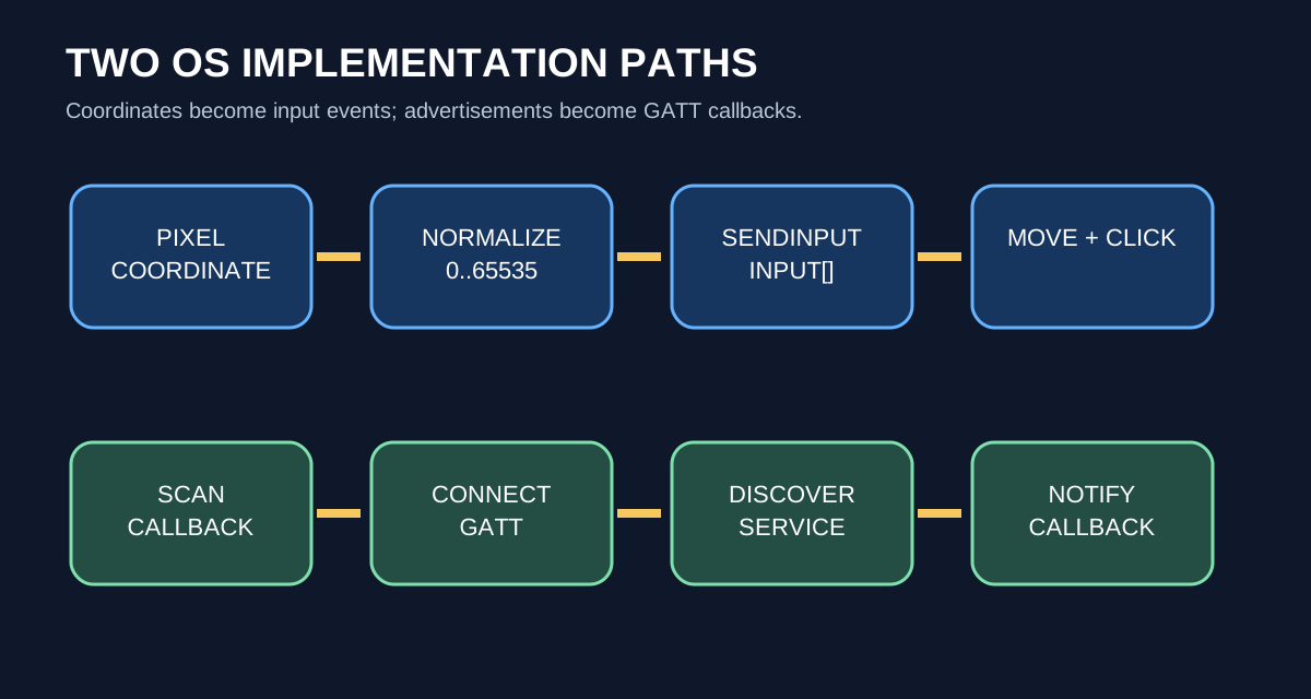
At the outermost Windows layer, an auto mouse is straightforward. Pick the screen pixel to click, normalize it to the 0–65535 absolute-coordinate range, then put move, left-button-down, and left-button-up records into an INPUT array for SendInput. Microsoft's SendInput reference describes this as serial insertion of keyboard and mouse events into the input stream.
MOUSEEVENTF_ABSOLUTE accepts normalized rather than literal pixel coordinates. On a multi-monitor desktop, pair it with MOUSEEVENTF_VIRTUALDESK and the virtual desktop's left, top, width, and height. For a non-fixed button, the next pipeline is screen capture, template matching or OCR, button-center calculation, then clickAt(). That is the technical backbone of UI automation.
SendInput is a User32 input-layer API. This article stays at OS-provided UI-event generation and screen-coordinate handling. UIPI and application-specific input handling remain runtime conditions to check.
2. Android Bluetooth LE: from scan callback to GATT notification
For headphones or a sensor, three Android classes carry the BLE implementation. BluetoothLeScanner discovers peripherals and returns results through ScanCallback. A discovered BluetoothDevice connects through connectGatt(). Connection, service discovery, reads, and notifications return through BluetoothGattCallback.
On Android 12 and newer, declare and request the following permissions at runtime. Android's Bluetooth permissions guide explains BLUETOOTH_SCAN and BLUETOOTH_CONNECT.
This Kotlin example finds an owned BLE test device by advertised name, connects, then locates a documented service and characteristic UUID and enables notifications. Replace the sample UUIDs with the device's published GATT contract or values first observed in nRF Connect; do not invent them for a product.
onConnectionStateChange() receives link state, onServicesDiscovered() gets the GATT table, and onCharacteristicChanged() receives data pushed by the device. API 33 added the ByteArray value callback signature; Android's BluetoothGattCallback reference documents why it is preferable.
3. When BLE will not connect: where nRF Connect, HCI, ATT, and Wireshark fit
Separate the layers instead of reciting tool names. nRF Connect is a mobile test app that scans peripherals and explores, reads, and subscribes to GATT services and characteristics. Use it to verify the UUID contract before debugging application code. ATT, the Attribute Protocol, is the data protocol through which GATT reads and writes characteristic values. HCI, the Host Controller Interface, is the packet layer between Android's Bluetooth host and the physical controller. Wireshark opens an HCI snoop capture to show whether advertising, connection, ATT reads/writes, and notifications actually occurred.
Start with framework and service state:
Then enable Enable Bluetooth HCI snoop log in Developer options and restart Bluetooth. AOSP's Bluetooth debugging guide documents dumpsys bluetooth_manager, btsnooz.py BUG_REPORT.txt > BTSNOOP.log, and HCI-snoop collection.
The diagnostic sequence becomes concrete. If nRF Connect cannot see the service, start with advertising, connection, or the peripheral GATT itself. If nRF works but the app does not, inspect permission, UUID, callback order, and descriptor write. If HCI contains a write but no notification, inspect peripheral firmware and characteristic subscription. Linking code, OS, and controller logs on one timeline is exactly where AI compresses discovery time.
4. Raspberry Pi car: join motor, sensor, and UART in one process
Before looking at code, separate the roles of the parts. This car has a Linux computer making decisions, GPIO carrying command signals, a motor driver switching current, and sensors or an MCU returning input.
| Term | Role in this stack | What to verify at the connection |
|---|---|---|
| Raspberry Pi | Main computer running Linux, Python, and networking | GPIO pinout, camera, /dev/tty*, Wi-Fi/Ethernet |
| GPIO | Low-voltage pins carrying digital or PWM command signals | BCM versus physical pin number and 3.3 V logic level |
| H-bridge | Power switch that reverses motor current for forward/reverse | Pi GPIO inputs (IN1/IN2/PWM) and a separate motor supply |
| TB6612FNG / L298N | Common module implementations of an H-bridge | enable/STBY, motor supply, and common ground |
| UART | TX/RX serial byte stream between devices | port name, baud rate, and crossed TX/RX wiring |
| MCU or sensor | Helper device reading field inputs such as distance, speed, or ADC | message format (such as JSON), sample interval, and power |
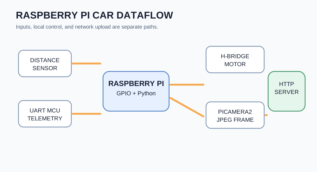
The minimum toy-car stack is therefore a Raspberry Pi, an H-bridge motor driver, a distance sensor, and a helper MCU or sensor over UART. When the Pi emits the logical command “forward at 45%” through GPIO, the H-bridge uses the separate motor supply to turn the wheels. The MCU returns sensor values over UART; the Pi combines those values with Python, network, and camera code. Do not attach a motor directly to GPIO; use an H-bridge such as a TB6612FNG or L298N. Raspberry Pi's GPIO hardware guide provides the same guidance and exposes pinout for local pin inspection.
The important question here is: when a sensor signal reaches the Pi, what actually wakes up? The answer depends on the sensor type. Connecting a sensor to a Raspberry Pi means choosing one of three paths.
| Sensor output | Path inside the Pi | What the program sees |
|---|---|---|
A digital line changing between 0 V and 3.3 V, such as a button, PIR, or sensor INT/DRDY pin |
GPIO pin → SoC GPIO controller → rising/falling edge → Linux GPIO event | Event callback such as when_pressed, or a gpiomon wait |
| A sensor or MCU sending bytes over I2C, SPI, or UART | I2C/SPI/UART peripheral → FIFO → hardware interrupt → Linux driver buffer | Blocking read() or readline() |
| An analog sensor producing a continuous voltage, such as a potentiometer | The Pi has no ADC, so an external ADC or MCU converts it to digital first | Read the converted value through SPI, I2C, or UART |
In other words, a changed voltage is detected first by the SoC GPIO block or a communications peripheral. GPIO inputs can be configured as rising/falling-edge or high/low-level interrupt sources. Linux passes the resulting event through a driver and file descriptor; a userspace program waits for the event or registers a library callback. Raspberry Pi's GPIO documentation states that GPIO inputs can be interrupt sources for the Arm, and its GPIO interrupt section distinguishes rising/falling edges from level interrupts.
Polling, blocking reads, and callbacks are different things. This distinction has to be clear before the sensor code can be read correctly.
| Code shape | Actual mechanism | Role in the car |
|---|---|---|
while True: sensor.distance; sleep(0.05) |
Poll current state every 50 ms | An HC-SR04-style measurement where the Pi must send a trigger first |
motor.forward(0.45) |
PWM output | A command to turn a wheel, not input reception |
uart.readline() |
Sleep until data arrives in the UART driver buffer | Receive MCU telemetry without wasting CPU |
sensor.when_pressed = handler |
Wait for a GPIO edge, then let a library run a userspace function | Receive new-data notifications from a sensor with INT or DATA_READY |
Strictly speaking, the Linux kernel does not directly call a Python function. The sequence is voltage change → GPIO hardware interrupt → kernel-driver event → a waiting userspace process or library thread wakes up → handler runs. gpiozero's when_pressed is an API that makes this final userspace callback convenient. Its input-event documentation separately demonstrates is_pressed polling, wait_for_press() blocking, and the when_pressed callback.
Step 1: identify pins and device files first
pinout maps physical pins to BCM numbers; /dev/ttyACM0 and /dev/ttyUSB0 are device files a USB/UART MCU creates in Linux. GPIO 5 means BCM number 5, not physical pin 5.
Step 2: poll sensors that must be asked, such as the HC-SR04
This example uses gpiozero.Motor for the H-bridge IN1/IN2 pins and DistanceSensor for an HC-SR04-style trigger/echo sensor. The HC-SR04 only returns a value after the Pi sends a trigger pulse and measures echo travel time, so 20 Hz polling is appropriate here. Pin numbers are BCM numbers; adapt them to real wiring, driver-board enable, and standby pins.
Step 3: receive sensors with an INT or DATA_READY pin through edge events
Accelerometers, ADCs, and some distance sensors expose an INT or DATA_READY pin to announce that a new measurement is ready. Connect that pin to Pi GPIO and there is no need to ask every 50 ms. For example, suppose a sensor emits an active-high DATA_READY pulse on BCM GPIO 5.
when_pressed is not the hardware ISR itself; it is a userspace callback. From the program's point of view, it is still a push model: the code runs when the sensor announces new data. The Linux GPIO character-device API sends rising/falling edge events to userspace with timestamps and sequence numbers. To inspect the lower layer first, observe real edges with libgpiod tools.
Step 4: receive UART through a blocking read
For an Arduino or sensor board on UART, send a line of JSON from the MCU and read it on the Pi. This is the simplest telemetry path between a board and a Linux application. readline() here is not busy polling that checks an empty buffer every 50 ms. The UART peripheral reports an arriving byte by interrupt; the Linux TTY driver puts it in a kernel buffer and wakes the sleeping readline() call.
Polling is therefore not the only choice. Use a GPIO edge event when a sensor has DATA_READY; use a blocking readline() when it streams over UART; use polling at an appropriate interval when an I2C sensor responds only after being asked. In a sensor datasheet, look not only for the measurement register but also for INT, DRDY, DATA_READY, and FIFO. That one line determines how the sensor, operating system, and Python control loop fit together.
5. Send camera frames to a server with Picamera2 and HTTP
Adding a camera lets the car send frames as well as scalar sensor data. On current Raspberry Pi OS, Picamera2 runs on the libcamera/rpicam stack. Raspberry Pi's camera documentation and the Picamera2 manual document the capture_array() path to a NumPy frame.
At first the server only needs to receive the frame and return a status code. Later it can separate motor commands through MQTT or return object-detection results for the Pi to consume. AI is particularly useful here because it joins rules scattered across GPIO pins, UART baud rates, camera formats, HTTP payloads, and system-service logs into one executable first draft.
Does embedded work feel difficult? I feel the same way. To implement the intended signal interpretation and behavior, one has to know the specifications of hardware sensors and their callback structures well enough to distinguish an appropriate polling structure from the shape of the sensed values. But seeing the boundary clearly is enough for the next step. Once we can see it, we can ask AI about it, question its answer again, and dive deeper.
The point of Part 3 is to see the thresholds between fields. Then we can finally ask AI about what those thresholds really are. AI already knows at least part of the answer. We have entered a time when people who did not even know where the threshold was can use AI to identify it, learn how to cross it, and begin to aim for a complete implementation.
Conclusion
In the past, taking on each field alone required a large amount of work and an enormous body of knowledge. Companies that build businesses around these skills must turn all of that expertise into revenue, which makes the industrial version of the problem harder still. Then AI arrived. Trained on extensive operating-system foundations, embedded code, virtualization techniques, open-source projects, languages, long-lived Python and scripting ecosystems, and design patterns, it can extend a developer's practical range dramatically. It can surface the Windows API sets needed to create a window, identify OS components and hardware-control interfaces, and propose a systematic path through permissions and firewall conditions. Keyboard and mouse HID control, screen capture, image processing, and real-time image analysis become far more approachable when those pieces are brought together.
The same is true when the hardware target is Android rather than Windows. AOSP, the Android Open Source Project, makes the foundation of the Android operating system publicly available. The AOSP architecture overview describes it as publicly available and modifiable Android source. That gives an AI-assisted developer a rich starting point for understanding mobile execution, driver structures, and their underlying principles. Mobile Bluetooth, USB-C interfaces, and NFC therefore become technical areas whose first principles can be reached much faster.
Raspberry Pi and Arduino systems built on Linux are no different. The embedded-driver work that connects Linux and physical boards once felt like an open secret; now the code, test environments, and tools are far easier to find and interrogate with AI. Python's once-distant ecosystem is likewise available to developers who previously worked mainly in Java or scripting environments, opening a practical route to C, C++, and Python. The AI vibe-coding market is still early, and developers may not yet have noticed how far their working range has expanded. Before that expanded capability is fully understood—or before AI replaces more of the work—the more useful question is how far we can push this unfamiliar technology. It is time to look more closely.
As the examples in this article show, a developer CLI workflow and AI coding tools let us ask and act in the order which class → which callback → which log → which port → which test, even in a new field. Once that flow is executed and corrected, the walls built by languages and platforms become substantially lower.